Real Time Streaming Video/Audio
ESP32 / ESP32-CAM
ILI9341 LCD Display & Touch
Sound sensor
Introdcution
Streamin Vidéo en temps réel sur des devices Arduino
Dans ce tuto nous allons commencer l'acquisition des données qui seront traitées par l'IA embarquée sur les devices IoT (IoT : Internet of things, AI: Artificail Intellilligence, AIoT: Artificial Intellignece of Things). Pour des raisons de vérification un rendu sera aussi réalisé sur ces mêmes devices. Dans cette première partie on traitera un flux vidéo, le flux audio fera l'objet de la deuxième partie plus bas.
Prérequis
Vous aurez besoin pour la réalisation de ce projet de- 2 cartes de développement esp32
- Une carte de développement esp32-cam
- Un écran LCD ili9341 tactile (ou pas)
- 2 sound sensors (microphones) type MAX4466
- 2 hauts parleurs 2W 8 Ohm type MLS3
- 2 amplificateurs audio type LM386
- L'IDE Arduino pour la compilation et le version des binaires sure les deux cartes
- De votre PC avec Python idéalement un Jupyter lab installé
- Et bien évidement de connecteurs, câbles usb, fils électriques .... ça va de soi.
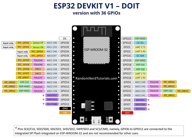
La Carte de développement ESP32
C’est définitivement ma carte préférée, non seulement pour le prix mais surout pour ses capacités en comparaison avec toutes les autres cartes que j'ai pu tester, de l'arduino oficiel (nano, uno ou méga), à la Raspberry Pico en passant par la pi 3, pi4 8 Go ainsi que d'autres copies Arduino Open Source (Adafrut notement).
Pour plus de détails sur les caractéristiques et les possibilités de cette carte vous pouvez voir le Site Officiel
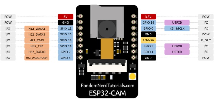
L'ESP32-CAM
C’est la même carte ESP32 équipée d'une caméra OV2640 et d'un lecteur de cartase SD (Ce qui au passage consomme la plupart des pins GPIO disponibles, il faudra pour disposer de quelques pin GPIO soit ne pas utiliser la carte SD soit comme dans ce projet l'associer à une autre ESP32, puis assurer l'interconnexion avec UAR (port série) ou en WIFI/BT, ce qui en fait une plateforme de 2 processures bi coeurs avec caméra, lecteur SD, XX pins GPIO à faible consommation électrique)
?
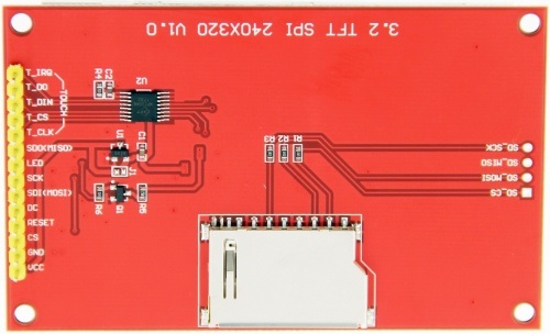
Câblage écran tactile ILI9342
Présentation de la carte
Pour l'affichage vidéo nous allons utiliser une carte ILI9341. Pour plus de détails sur les spécifications de cette carte d'affichage vous pouvez consulter ce Manuel depuis ce Wiki Assez complet
| Number | Pin Label | Description |
| 1 | VCC | 5V/3.3V power input |
| 2 | GND | Ground |
| 3 | CS | LCD chip select signal, low level enable |
| 4 | RESET | LCD reset signal, low level reset |
| 5 | DC/RS | LCD register / data selection signal,
high level: register, low level: data |
| 6 | SDI(MOSI) | SPI bus write data signal |
| 7 | SCK | SPI bus clock signal |
| 8 | LED | Backlight control, high level lighting,
if not controlled, connect 3.3V always bright |
| 9 | SDO(MISO) | SPI bus read data signal, if you do not need to the read function, you can not connect it |
| (The following is the touch screen signal line wiring, if you do not need to touch function or the module itself does not have touch function, you can not connect them) | ||
| 10 | T_CLK | Touch SPI bus clock signal |
| 11 | T_CS | Touch screen chip select signal, low level enable |
| 12 | T_DIN | Touch SPI bus input |
| 13 | T_DO | Touch SPI bus output |
| 14 | T_IRQ | Touch screen interrupt signal, low level when touch is detected |
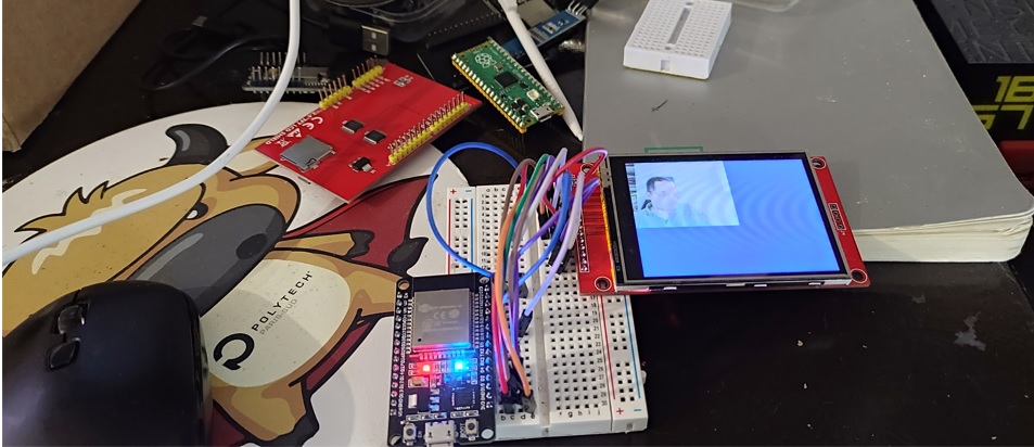
Câblage avec la carte ESP32
Ce tuto n'a pas pour objectif de détailler le fonctionnement de cette carte, je vais tout simplemnt utiliser une librairie open source TFT_eSPI pour les opération d'affichage, ni de détailler le fonctionnement du porocessus de codage et de décodage des images jpeg, l'esp32cam produit nativement des ilages jpeg, le décodage se fera avec une librairie arduino open source optimisée IoT Arduino TJpg_Decoder library elle même basée sur le TJpgDec - Tiny JPEG Decompressor , mes premiers tests ont utilisés la JPEGDecoder
Si besoin de plus de détails sur la configuration de l'IDE Arduino pour la compilation et l'upload du code sur vos cartes esp c'est par ici à moins que vous voulez tout écrire en Python et passer par un MicroPython Integré qui sera l'objet de mon prochain Tuto

Code Source
/*
  Imed MAGROUNE 01/2022
*/
/*

#define TFT_MISO 19
#define TFT_MOSI 23
#define TFT_SCLK 18
#define TFT_CS   15  // Chip select control pin
#define TFT_DC    2  // Data Command control pin
#define TFT_RST   4
 * *
 */
/*-------------------------- Include ----------------------*/
#include < WiFi.h >
#include < WiFiClient.h >
#include < SPI.h >


#include < TFT_eSPI.h >
#include < TJpg_Decoder.h >
#
TFT_eSPI tft = TFT_eSPI();

uint8_t img[70000];
uint32_t  imglen;

IPAddress myIP;
//Timer
const char *ssid = "deepnologic";
const char *password = "00001111";

#define WIFI_TIMEOUT_MS 20000 // 20 second WiFi connection timeout
#define WIFI_RECOVER_TIME_MS 30000 // Wait 30 seconds after a failed connection attempt

/*---------------------------------------- */
// Global variables available to BOTH processors 0 and 1

TaskHandle_t Task1;
const uint8_t* arrayName;           // Name of FLASH array containing Jpeg
bool doDecoding = false;            // Mutex flag to start decoding
bool mcuReady = false;              // Mutex flag to indicate an MCU block is ready for rendering
uint16_t mcuBuffer[16*16];          // Buffer to grab a snapshot of decoded MCU block
int32_t mcu_x, mcu_y, mcu_w, mcu_h; // Snapshot of the place to render the MCU

// This next function will be called by the TJpg_Decoder library during decoding of the jpeg file
// A copy of the decoded MCU block is grabbed for rendering so decoding can then continue while
// the MCU block is rendered on the TFT. Note: This function is called by processor 0
bool mcu_decoded(int16_t x, int16_t y, uint16_t w, uint16_t h, uint16_t* bitmap)
{
   // Stop further decoding as image is running off bottom of screen
  if ( y >= tft.height() ) return 0;

  while(mcuReady) yield(); // Wait here if rendering of last MCU block to TFT is still in progress

  memcpy(mcuBuffer, bitmap, 16*16*2); // Grab a copy of the MCU block image
  mcu_x = x;                          // Grab postion and size of MCU block
  mcu_y = y;
  mcu_w = w;
  mcu_h = h;
  mcuReady = true; // Flag to tell processor 1 that rendering of MCU can start

  // Return 1 to decode next Jpeg MCU block
  return 1;
}

// This is the task that runs on processor 0 (Arduino sketch runs on processor 1)
// It decodes the Jpeg image
void decodeJpg(void* p) {
  // This is an infinite loop, effectively the same as the normal sketch loop()
  // but this function and loop is running on processor 0
  for(;;) {
    // Decode the Jpeg image
    if (doDecoding) { // Only start decoding if main sketch sets this flag
      TJpgDec.drawJpg(0, 0, arrayName, sizeof(img)); // Runs until complete image decoded
      doDecoding = false; // Set mutex false to indicate decoding has ended
    }
    // Must yield in this loop
    yield();
  }
}


/*--------------------------------*/

void setup() {
  Serial.begin(115200);
 //Create task decodeJpg to run on processor 0 to decode a Jpeg
  xTaskCreatePinnedToCore(decodeJpg, "decodeJpg", 10000, NULL, 0, NULL, 0);

  tft.begin();
  tft.setRotation(3);
  tft.fillScreen(TFT_NAVY);

  tft.setTextSize(2);
  tft.setTextColor(TFT_WHITE, TFT_NAVY);
  tft.drawString("Initializing", 10, 10, 2); // Font 4 for fast drawing with background
  initeeprom();
  readconf();
  WiFi.macAddress(mac);

  initap();

    // wdt
    esp_task_wdt_init(3600,true);
    esp_task_wdt_add(NULL);


    imglen=0;

    // The jpeg image can be scaled by a factor of 1, 2, 4, or 8
  TJpgDec.setJpgScale(1);

  // The byte order can be swapped (set true for TFT_eSPI)
  TJpgDec.setSwapBytes(true);

  // The decoder must be given the exact name of the mcu buffer function above
  TJpgDec.setCallback(mcu_decoded);

    Serial.println("OK");
 }

void loop() {


     server.handleClient();

     checknet2();

     // Only render MCU blocks if decoding is in progress OR an MCU is ready to render
     // Note: the OR mcuReady is required so the last block is rendered after decoding has ended
  while(doDecoding || mcuReady) {
    if (mcuReady) {

      tft.pushImage(mcu_x, mcu_y, mcu_w, mcu_h, mcuBuffer);
      mcuReady = false;
    }
    // Must yield in this loop
   // -----------!!!!!!!!!!
   yield();
  }


}
void initap()
{
  Serial.println();
  Serial.println("Configuring access point...");
   WiFi.disconnect(true);
  // You can remove the password parameter if you want the AP to be open.
  WiFi.softAP(ssid, password);
  myIP = WiFi.softAPIP();
  delay(100);
  Serial.println("Set softAPConfig");
  IPAddress Ip(192, 168, 111, 1);
  IPAddress NMask(255, 255, 255, 0);
  WiFi.softAPConfig(Ip, Ip, NMask);
  myIP = WiFi.softAPIP();
  Serial.print("AP IP address: ");
  Serial.println(myIP);

  server.on("/", handleRoot);
  /*server.on("/login", handleLogin);
  server.on("/inline", [](){
    server.send(200, "text/plain", "this works without need of authentification");
  });
  server.onNotFound(handleNotFound);*/
  //here the list of headers to be recorded
  const char * headerkeys[] = {"User-Agent","Cookie"} ;
  size_t headerkeyssize = sizeof(headerkeys)/sizeof(char*);
  //ask server to track these headers
  server.collectHeaders(headerkeys, headerkeyssize );
  server.begin();
  Serial.println("HTTP server started");
  initudp();

}

//wifi event handler
void WiFiEvent(WiFiEvent_t event){
    switch(event) {
      case SYSTEM_EVENT_STA_GOT_IP:
          //When connected set
          Serial.println("WiFi Event connected ");
          // Serial.println(WiFi.localIP());
          //initializes the UDP state
          //This initializes the transfer buffer
          break;
      case SYSTEM_EVENT_STA_LOST_IP:
      case SYSTEM_EVENT_STA_DISCONNECTED:
          Serial.println("WiFi disconnected! rebooting ");
          if(deja_connecte==1)
            ESP.restart();
          break;
    }
}
i
void initudp(){
   udp.begin(11672);
}

void checknet2()
{
//Serial.print(".");
byte dst[1500];
int dsize;

   udp.parsePacket();
   String cmd;

   if ((dsize=udp.read(packetBuffer,1500)) > 0) {
    Serial.println("!!");
	  memcpy(dst,packetBuffer,1500);
	  // Serial.println(udp.remoteIP());
	  char cip[210];
	  // sprintf(cip," from %d.%d.%d.%d size=%d %d/%d  %4X %4X",udp.remoteIP()[0],udp.remoteIP()[1],udp.remoteIP()[2],udp.remoteIP()[3], dsize , dst[0], dst[1], dst[2], dst[3] );

    // Serial.println(cip);

   if(dst[0]==255)
   {
    // Serial.println("Return");
     return;
   }

   // sprintf(cip,"%4X %4X %4X %4X ",dst[2], dst[3],dst[4], dst[5]);

	 if(dst[0]==0)
   {
     totrec=0;
      memcpy(img,dst+2,dsize-2);
      imglen=dsize-2;
   }
   else
   {
    totrec++;
     if(dst[0]==dst[1] && totrec==dst[1])
     {
      memcpy(img+imglen,dst+2,dsize-2);
      imglen+=dsize-2;

  // The order here is important, doDecoding must be set "true" last after other parameters have been defined
  arrayName  = img; // Name of FLASH array to be decoded
  mcuReady   = false; // Flag which is set true when a MCU block is ready for display
  doDecoding = true;  // Flag to tell task to decode the image


     }
     else
     {
      memcpy(img+imglen,dst+2,dsize-2);
      imglen+=dsize-2;
     }

    }
   }
}
Test avec envoi depuis le PC
Avant d'aller plus loin, testons la réception et l'affichage avec des frames envoyés depuis le P
#pip install opencv-python if needed
import cv2
import numpy as np

import socket

localIP     = "192.168.111.2"
localPort   = 1167
sock = socket.socket(family=socket.AF_INET, type=socket.SOCK_DGRAM)
sock.bind((localIP, localPort))

 Create a VideoCapture object
cap = cv2.VideoCapture(0)

# Check if camera opened successfully
if (cap.isOpened() == False):
  print("Unable to read camera feed")

# Default resolutions of the frame are obtained.The default resolutions are system dependent.
# We convert the resolutions from float to integer.
frame_width = int(cap.get(3))
frame_height = int(cap.get(4))
print("width=",frame_width, " height=",frame_height )

cap.set(cv2.CAP_PROP_FRAME_WIDTH, 80)
cap.set(cv2.CAP_PROP_FRAME_HEIGHT, 60)

frame_width = int(cap.get(3))
frame_height = int(cap.get(4))
print("width=",frame_width, " height=",frame_height )
# Define the codec and create VideoWriter object.The output is stored in 'outpy.avi' file.
#out = cv2.VideoWriter('outpy.avi',cv2.VideoWriter_fourcc('M','J','P','G'), 10, (frame_width,frame_height))
#

packet=bytearray(1202);

while(True):
  ret, frame = cap.read()

  if ret == True:

    # Write the frame into the file 'output.avi'
    #out.write(frame)

    # Display the resulting frame
    cv2.imshow('frame',frame)
    #
    #Send frame to esp
    image_bytes = cv2.imencode('.jpg', frame)[1].tobytes()
    imsize=len(image_bytes)
    nbpackets=imsize//1200
    packet[1]=nbpackets
    #print(imsize,nbpackets)
    for i in range(nbpackets):
        packet[0]=i
        packet[2:]=image_bytes[i*1200:i*1200+1200]
        sent = sock.sendto(packet, ('192.168.111.1', 1672))
        #print(packet[0],packet[1])
    packet[0]=packet[1]
    packet[2:]=image_bytes[nbpackets*1200:]
    #print(packet[0],packet[1],imsize%1200)
    sent = sock.sendto(packet[:imsize%1200], ('192.168.111.1', 1672))
    # Press Q on keyboard to stop recording
    if cv2.waitKey(1) & 0xFF == ord('q'):
      break


  # Break the loop
  else:
    break

# When everything done, release the video capture and video write objects
cap.release()
#out.release()

# Closes all the frames
cv2.destroyAllWindows()
Suite en route
Suite dans la partie 2 :REX
- La carte Raspberry PICO ne peut dépaser les 8000 Hz pour le signal PWM, donc non adaptée au rendu audio
- La carte Raspebryy PI n'a que des GPIO en digital, pas DAC et donc pas d'acquisition audi possible
- La carte esp32cam n'a plus de DAC si le wifi est activé d'où le besoin de deux cartes